You have seen die-cut boxes, book covers, and packaging inserts countless times. But have you ever stopped to think about how they are actually made? The process is more sophisticated than simply pressing a sharp blade through paper.
A die cutting machine transforms a flat sheet of paper, board, or plastic into a precisely shaped finished piece—complete with creases, cutouts, and clean edges. Understanding how this happens, step by step, helps you appreciate what goes into your packaging and why certain results are achievable while others are not.
This article walks through the entire die cutting process, from the moment the sheet enters the machine to the moment the finished product comes out.
Before diving into the step-by-step process, it helps to understand what a die cutting machine is and what it is designed to accomplish.
A die cutting machine uses die cutting knives, steel rules, metal molds, or steel wires to apply pressure through a printing plate, cutting printed products or paperboard into specific shapes. If the entire printed sheet is cut into individual product shapes, the operation is called die cutting; if steel wires are used to press crease lines or grooves, it is called creasing.
The machine operates on a simple mechanical principle: a flat or rotating surface applies controlled pressure to force a cutting die through the material. In a flatbed die cutter, the cutting die is attached to a lower platen. When the machine is activated, the upper platen comes down with significant force, pressing the material against the cutting die.
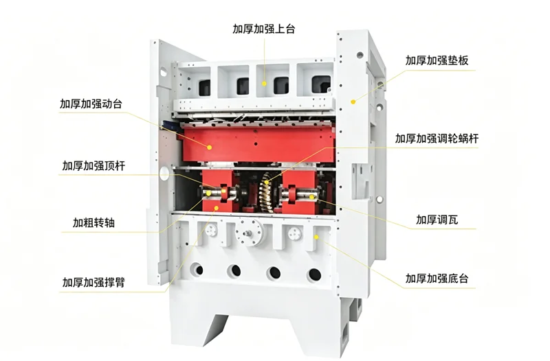
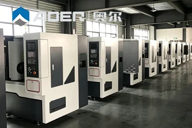
AOER’s die cutting machines, for example, are built with an H250 high-strength material frame combined with integrated casting technology, with peak pressure output reaching 3000kN. This level of force enables clean, non-serrated cutting of paperboard, corrugated paper, and industrial plastic sheet materials up to 7mm thick.
What this means for your production: The pressure capability of a machine directly determines what materials you can process and how cleanly they will cut. A machine with insufficient pressure will leave fuzzy edges or fail to cut through entirely—regardless of how sharp the die is.
For production environments where material thickness varies, understanding the pressure capabilities of different machine classes helps when selecting equipment. See how automatic and manual presses compare in their pressure specifications: review pressure capacity ranges across finishing equipment categories.
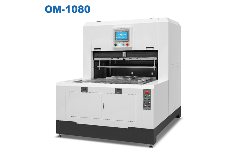
Every die cutting job starts with the same action: getting the sheet into the machine. But how this happens varies significantly between manual and automatic machines.
On a manual die cutting machine, the operator feeds each sheet individually by hand. The operator positions the sheet against registration guides—typically a front lay (stopping forward movement), and side lay (stopping sideways movement)—to ensure consistent positioning before each press cycle.
Manual feeding is straightforward but labor-intensive. A typical manual press operates at 23–26 strokes per minute, meaning the operator must feed a new sheet for every single cycle. This makes manual feeding suitable for short runs and prototyping, but limits throughput for large-volume production.
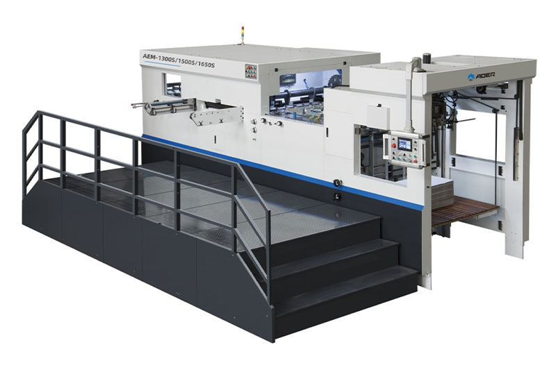
Automatic die cutting machines use mechanized feeding systems that dramatically reduce labor requirements and increase consistency. The most common automatic feeding methods include:
| Feeder Type | How It Works | Best For |
|---|---|---|
| Top suction feeder | Suction nozzles lift the top sheet from a stack and feed it into the machine | Thin to medium board, mixed materials |
| Lead edge feeder | A gripper system grabs the leading edge of each sheet and pulls it forward | Thick paperboard and corrugated board |
| Flyer feeder | A specialized feeder for large-format die cutting machines | Large-format board processing |
AOER’s automatic die cutting machines feature fully automatic feeding mechanisms with guide rail type pre-packed pallets that improve feeding efficiency, as well as servo motor paper conveying that prevents overlap of two sheets.
What this means for your shop: The feeder is the gateway to your entire production line. If the feeder struggles—with frequent jams, misfeeds, or inconsistent sheet positioning—nothing else in the process can compensate. A reliable feeder is the foundation of consistent die cutting quality.
External reference: According to TAPPI’s Technical Information Paper on paper feeding, a minimum coefficient of friction is required to prevent double-feeding of sheets. Different materials have different friction coefficients—and when your feeder is not designed for your specific material mix, feeding problems become inevitable.
Once the sheet enters the machine, it must be positioned with extreme accuracy before the cut occurs. Even a fraction of a millimeter of misalignment can ruin an entire sheet.
In automatic flatbed die cutting machines, the sheet is delivered by the feeder to the front lay and side lay, mechanical stops that precisely position the sheet. Once positioned, the sheet is gripped by a paper feeding mechanism (often a gripper bar or chain system) that carries it into the die cutting section.
The open-delay function available on some machines allows operators to set personalized indentation delay ranges (0–50 milliseconds) based on material characteristics, adapting to die cutting requirements for different material weights (80–1500 grams).
Poor registration—where the cut does not align with pre-printed graphics or where creases fall in the wrong position—creates scrap. In high-volume production, even a 1% registration error rate can translate into thousands of wasted sheets annually.
AOER’s automatic machines are equipped with precision control systems that maintain accurate pressure and positioning to reduce defective products. The equipment’s vibration amplitude is controlled within 0.1mm, ensuring cutting accuracy during high-speed operation at ±0.05mm.
What this means for your production: Registration accuracy determines whether your finished product looks professional or defective. A machine that cannot hold registration consistently will produce inconsistent results regardless of how skilled the operator is.
For finishing departments where registration accuracy is critical for quality-sensitive applications, reviewing the complete workflow helps identify potential improvement areas. See how workflow planning addresses registration and quality control: examine finishing workflow approaches for quality-critical applications.
This is the core of the operation—the moment when pressure is applied, and the material is cut or creased.
In a flatbed die cutting machine, the die (a flat plate containing cutting rules and creasing wires) is mounted on the lower platen. The upper platen—a heavy, flat steel plate—descends with tremendous force, pressing the sheet against the die.
The die itself contains two types of elements:
Cutting rules: Sharp steel blades that cut entirely through the material
Creasing wires (or scoring rules): Blunt-edged steel that compresses the material to create fold lines without cutting
The peak pressure output on heavy-duty machines reaches 3000kN, enabling clean cutting of materials up to 7mm thick. The H250 high-strength material frame and integrated casting technology ensure that this force is applied uniformly across the entire sheet surface.
Modern machines offer flexibility in how the cutting action is applied:
Single-sheet die cutting: Each sheet is cut individually in a discrete cycle—the sheet stops, the platen closes, and the cut is made
Continuous die cutting: Sheets are fed and cut in rapid succession with minimal pause between cycles
AOER’s machines enable seamless switching between single-sheet and continuous die-cutting modes through an integrated 10.1-inch touch screen for intuitive parameter adjustment—including real-time monitoring of cutting depth, pressure, and speed.
The machine’s structural integrity is critical to consistent cutting quality. AOER’s machines use H250 material monoblock cast frames and bronze alloy sliding bearings. The core transmission components are equipped with high-quality cast copper alloy sliding bearings, with operating noise as low as 65 decibels (industry average is 80 decibels).
What this means for your shop: A rigid frame and high-quality bearings ensure that the pressure applied during cutting is consistent across the entire sheet. A machine with a flexible frame or worn bearings will produce uneven cuts—clean in some areas, incomplete in others.
After the sheet has been cut, the next challenge is separating the finished product from the surrounding waste material. This step is called stripping or waste removal.
In a fully automatic process, after die cutting, the sheet is advanced by the gripper system (often a chain-driven gripper bar or tooth row) to the stripping station. At this station, the waste portions of the sheet—the material outside the finished product shape—are removed.
Stripping can be accomplished through several mechanisms:
Mechanical stripping pins or fingers that push waste out from above
Suction systems that pull waste away
Ejection rubber (sponge) mounted directly on the die that forces material separation immediately after cutting
AOER offers machines with automatic stripping devices that reduce manual intervention and improve yield. Some models feature integrated waste stripping systems that enhance efficiency for precision cutting applications.
Poor stripping creates two problems:
Waste that stays attached to the finished product requires manual removal—a slow, labor-intensive process
Waste that remains in the die can cause damage on subsequent cycles
What this means for your production: A machine that cuts cleanly but strips poorly will still create bottlenecks. The stripping system is as important as the cutting system for overall throughput.
The final step in the die cutting process is delivering finished products to the collection point.
After stripping, the finished pieces and any remaining waste are transported to the delivery section of the machine. In automatic machines, this is typically accomplished by the same gripper system that carried the sheet through the previous stages.
The delivery section separates finished products from any residual waste and stacks or collects them for further processing. Some machines include non-stop delivery systems that allow continuous operation without pausing to remove finished stacks.
AOER’s automatic machines feature optimized process flows that reduce energy consumption and waste generation. The entire series is equipped with detachable mold heads and a quick tool replacement structure, reducing tool replacement time to 15 minutes (traditional models require 40 minutes).
Depending on the application, finished products may proceed to:
Stacking and packaging: For finished boxes or covers ready for assembly
Further finishing: Such as folding, gluing, or hot stamping
Quality inspection: Visual or automated inspection for defects
What this means for your shop: The delivery system determines how efficiently finished products exit the machine. A bottleneck at delivery—whether from slow stacking or frequent jams—limits overall throughput regardless of how fast the machine cuts.
Here is the complete die cutting process in sequence:
| Step | What Happens | Key Component |
|---|---|---|
| 1. Sheet feeding | Sheets are fed into the machine—manually or automatically | Feeder (top suction, lead edge, or flyer) |
| 2. Registration | Sheet is positioned against front and side panels for accurate alignment | Front lay, side lay, gripper system |
| 3. Die cutting | Upper platen descends with force, pressing sheet against die | Platen, die, frame (H250 material) |
| 4. Stripping | Waste material is separated from finished product | Stripping pins, suction, ejection rubber |
| 5. Delivery | Finished products are collected and stacked | Delivery system, stacker |
You now have a clear picture of how a die cutting machine works—from the moment a sheet enters the feeder to the moment finished products emerge at the delivery end. Each step in the process plays a critical role in determining final quality and throughput.
The key takeaways:
Feeding and registration determine whether the cut happens in the right place
Die cutting pressure and frame rigidity determine whether the cut is clean and consistent
Stripping determines whether waste removal is reliable or creates bottlenecks
Delivery determines how efficiently finished products exit the machine
When evaluating die cutting equipment, consider how each stage of the process is addressed in the machine design. A machine with excellent cutting capability but poor stripping will still create production headaches. Similarly, a machine with fast feeding but inconsistent registration will produce scrap.
Once you have identified your typical material types, batch sizes, and quality requirements, comparing specific machine configurations becomes the logical next step. Different machine series emphasize different strengths—some prioritize speed and automation for high-volume production, while others focus on flexibility and ease of setup for short-run work.
Automatic vs Manual Die Cutting for Book Covers
Die Cutting Pressure & Stripping Force Explained
Flatbed or Rotary Die Cutting for Your Shop?
Five Signs Your Post-Press Line Needs a Feeder Upgrade
Quick-Change Die System for Short Runs
GET A QUOTE