You have likely experienced this frustration: the die cutting press is set up, the sheet feeds in, and the cut looks clean. But when the sheet moves to the stripping section, the waste does not come off cleanly—it hangs on, jams the machine, or worse, pulls the finished product apart. Alternatively, the stripping works perfectly, but the die cutting pressure was so high that it compressed the board excessively, leaving permanent marks on the cover.
These two forces—die cutting pressure and stripping force—are closely linked but often misunderstood. Die cutting pressure is what actually cuts or creases the material. Stripping force is what separates the finished piece from the surrounding waste after the cut is made.
This article explains what each force actually does, how they interact, and why finding the right balance for your material mix is essential for consistent output quality and tooling longevity.
Die cutting pressure is the force applied by the machine’s platen (flatbed) or rotating cylinders (rotary) to push the cutting rules through the material. In flatbed die cutting, the upper platen presses the entire sheet against the die in a single reciprocating motion. In rotary die cutting, the die cylinder rolls against an anvil cylinder, creating a continuous line of contact that progressively cuts the material as it passes through the nip.
A die cutting machine uses die cutting knives, steel rules, metal molds, or steel wires to apply pressure through a printing plate, cutting printed products or paperboard into specific shapes. If the entire printed sheet is cut into individual product shapes, it is called die cutting; if steel wires are used to press crease lines or grooves, it is called creasing.
What this means for your shop: Die cutting pressure is not a single number. It depends on three variables: the total length of cut (how much knife contact your die has), the thickness of your material, and the inherent shear resistance of that material.
For a shop running a simple box die with 20 meters of total knife length, the pressure requirement is different from a complex shaped die with 50 meters of knife line—even if both use the same material. Likewise, switching from 0.8mm coated paperboard to 2.5mm greyboard multiplies the required pressure, often several times over.
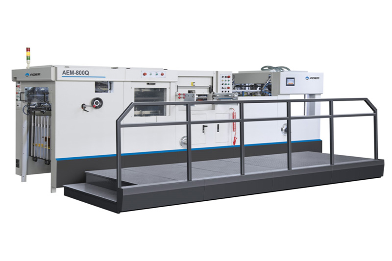
For production environments where material thickness varies widely between production runs, understanding how different machine frame constructions withstand peak pressure loads helps when comparing equipment options. See how automatic hot stamping machines are engineered for varying board thicknesses.
While most shops rely on experience and test sheets (trial-and-error) to set pressure, understanding the underlying calculation helps explain why certain jobs take longer to dial in than others.
Several published formulas describe the relationship between required die cutting force and the factors that influence it. One commonly cited theoretical formula is P = KσA, where P is the required die cutting force, σ is the unit-area shear stress value during pressing, and A is the actual separation area—calculated based on material thickness and cutting perimeter. K is a correction factor that accounts for actual processing conditions and various technical influences, with a range between 0.76 and 1.34.
An alternative expression, P = K1 × L × F, relates die cutting pressure to the total cutting perimeter L (including both cuts and creases) and a material-specific factor F. A 2023 technical article on die cutting pressure theory similarly notes that required die cutting force can be calculated using the formula P = KσA, where K ranges between 0.76 and 1.34.
| Factor | What It Means | Practical Implication |
| L (Cutting perimeter) | Total length of all knife edges and creasing rules in your die | A complex die with 50m of knife line needs roughly 2.5× the pressure of a simple 20m die |
| Material thickness | Thicker materials require more force to shear | Doubling thickness often more than doubles pressure requirement |
| Material type | Different papers have different shear strengths | Coated board versus kraft board—same thickness but different behavior |
| K factor (0.76–1.34) | Adjusts for die sharpness, backing condition, and other variables | Wide range explains why test sheets are necessary, even with calculations |
This wide K factor range—from 0.76 to 1.34—explains why two shops running the same die on the same material might end up with different optimal pressure settings. Die sharpness, rubber ejection sponge condition, backing plate flatness, and even ambient humidity all affect the actual force required.
Practical takeaway: The formula helps you understand relationships, but your actual pressure setting should always be validated by test sheets. A well-maintained die with sharp knives can cut cleanly at significantly lower pressure than a worn die—typically 20–30% lower, which extends the die life considerably.
For operators working with coated paperboard, a rough thickness estimation guideline appears in industry references: for materials below 200 grams, thickness (mm) ≈ grammage × 0.0009 ± 0.05mm; for materials above 200 grams, thickness (mm) ≈ grammage × 0.0011 ± 0.05mm. These approximations provide starting points for initial pressure guesses before test sheet validation.
Machine manufacturers often specify maximum press force in tons or kilonewtons. A typical mid-size automatic flatbed die cutter might offer up to 300 tons of cutting force. This capacity determines the maximum material thickness and complexity you can process. If your die requires 280 tons to cut cleanly and your machine maxes out at 250 tons, you will experience incomplete cuts or significantly accelerated die wear regardless of how carefully you set up.
While die cutting pressure has received most of the attention in technical literature, stripping force is arguably just as important for daily production efficiency. Stripping force refers to the energy required to separate the finished product from the surrounding waste material after the cut has been made.
In a flatbed die cutting operation, the stripping process typically advances the die-cut sheet horizontally to a stripping position where the waste portions overlie a stripping die with openings that correspond to the shape of the waste—but slightly larger—while the remainder of the stripping die supports the finished blank.
Stripping can be accomplished through several mechanisms: mechanical pins or fingers that push waste out from above, suction systems that pull waste away, or ejection rubber (sponge) mounted directly on the die that forces material separation immediately after cutting.
In metal stamping applications, stripping force is generally calculated as a percentage of the cutting force. Industry references indicate that stripping force typically ranges between 3% and 8% of the blanking force, depending on material characteristics and die geometry. While the percentages differ for paper and board applications (where materials are less elastic), the principle is similar: stripping force is proportional to cutting force but requires different consideration because it relates to friction and adhesion rather than shear.
What this means for your shop: A low stripping force setting leaves waste hanging—which jams the machine or requires manual cleanup. A high stripping force setting, achieved by oversize rubber or aggressive ejectors, can damage delicate products, particularly thin-walled boxes or intricate die-cut shapes. Finding the middle ground is essential.
| Aspect | Die Cutting Pressure | Stripping Force |
| When applied | During the cut (platen closing) | After the cut (platen opening, or separate stripping station) |
| What it overcomes | Material shear strength | Friction and adhesion between cut edges |
| Too low | Incomplete cuts, hanging fibers | Waste stays attached, jams machine |
| Too high | Die deformation, crushed board, accelerated wear | Product damage, delamination, fragile parts broken |
| Primary adjustment | Machine pressure setting, backing sheet thickness | Rubber durometer, rubber height, ejector pin placement |
The ideal scenario is the smallest die cutting pressure that still produces a clean cut across the entire sheet, combined with the minimum stripping force needed to reliably remove waste without damaging the product. Operating practice notes that the ideal die cutting pressure achieves clean separation of waste at the cut edges while keeping machine pressure at its minimum, which reduces die wear and ensures clean cut edges that strip easily.
For finishing departments where stripping defects create production bottlenecks or quality defects, analyzing the full post-press workflow helps pinpoint root causes linked to pressure or stripping performance. See how workflow planning resolves downstream finishing challenges: explore stripping and blanking machine workflow solutions for quality-critical production applications.
Incorrect pressure settings are among the most common causes of premature die failure and material waste. Understanding these failure modes helps shops justify the time spent on careful setup.
Setting pressure too high creates several problems:
Die deformation: Steel rules can bend or fracture under repeated excessive force
Crushed board: Thick paperboard can be permanently compressed, leaving visible marks
Accelerated wear: Each over-pressure cycle accelerates edge dulling
Backing plate damage: Cutting through the material into the backing plate creates grooves that cause inconsistent cuts on subsequent jobs
Industry guidance on die cutting troubleshooting notes that if the die cutting pressure is not properly adjusted—such as improper spot pressing or packing—problems like rough edges or fuzzing will occur. The pressure at the steel knife edge should be controlled to the minimal force required to cut the waste cleanly. If the pressure is adjusted too high or too low, it can cause the paper to become brittle or the crease lines to crack.
Insufficient pressure fails to cut completely through the material. Operators sometimes respond by running the job again, which doubles setup time and risks register shifts. Partial cuts also create a “hinge” effect—material still attached by thin fibers—which then tears irregularly during stripping, leaving fuzzy edges or partially attached waste.
Industry best practice: select the correct steel knife for the material, check the knife edge regularly and replace it when worn, and appropriately increase die cutting pressure if needed.
Even if total pressure is correct, uneven distribution causes localized problems. Dies with unbalanced knife placement—heavy concentration of cutting rules on one side—can cause the platen to tilt during pressing. Lightly distributed knife and rule patterns can cause the movable platen to tilt under cutting force. In such cases, adding balancing knife or rule lines to the die plate helps distribute force evenly.
Uneven pressure also results from the backing plate not being perfectly flat. Thin spots produce incomplete cuts in certain sheet areas; thick spots crush the material in others.
Practical implication: Regular maintenance of the backing plate (ensuring flatness within factory specifications) and careful die layout design are as important as the total pressure number. A flatbed press producing 300 tons of force is useless if that force is concentrated on one corner of the die.
In many shops, stripping problems generate more downtime than die cutting pressure issues. Here are common scenarios and their root causes.
Complex dies with small interior cutouts—cosmetic compact interiors, electronic device cutouts, pharmaceutical blister packaging—create waste pieces that are physically small. These pieces have limited surface area for ejection rubber to push against. If stripping force is insufficient, small waste remains lodged in the die, causing next-sheet damage.
Solution: Dedicated stripping pins or suction systems for small-hole applications, rather than relying solely on rubber ejection. One industry source notes that waste removal holes should be sized appropriately—the stripping hole should be approximately 1.5 to 2.0 mm larger than the waste piece. Holes that are too large cause the entire cut sheet to fall apart during stripping; holes that are too small fail to eject waste properly.
Rectangular outer waste frames and long narrow waste strips—common in box die cutting—can flex during stripping rather than eject cleanly. These flexible waste pieces are prone to catching on ejection pins or folding into the stripping station.
Solution: Strategic placement of “bridges” or tie-bars in the die design that hold long waste pieces together as larger units, making them more rigid and easier to eject as a single piece. Some shops add extra ejection pins specifically targeting the midpoint of long strips.
Gloss-coated papers and laminated boards present a different challenge: the coating or film layer creates higher friction between cut edges. The adhesive-like behavior of coating against steel rules increases stripping force requirements significantly—sometimes doubling the force needed compared to uncoated material of equal thickness.
Solution: Low-friction coatings on stripping pins, sharper knife angles to reduce contact area, or modified ejection rubber durometer (harder rubber for coated stocks) can mitigate this issue.
For metal stamping applications, a general rule documented in stamping industry literature suggests calculating shear force for punching, then estimating stripper pressure at approximately 5% of that value. For paper and board applications, percentages vary more widely due to material compressibility, but the principle remains: start with a low stripping force setting and incrementally increase until waste removal becomes reliable—then stop immediately.
External reference: The Die Makers Handbook notes a general rule: calculate shear force of punching and stripper pressure at 5%. When forming, calculate forming force and multiply by 1.5 for stripper force. While this applies to metal stamping rather than paper die cutting, the proportional logic—stripping force is a fraction of cutting force—applies to both industries.
While every die and material combination requires individual tuning, these rough starting points help shops establish baseline settings before fine-tuning through test sheets.
| Material Type | Typical Thickness Range | Relative Pressure Index (Thin Paper = 1) | Stripping Difficulty |
| Thin paper (80–150 gsm) | 0.07–0.15mm | 1× | Low |
| Coated paperboard (250–350 gsm) | 0.25–0.40mm | 2–3× | Moderate |
| Uncoated book board (400–800 gsm) | 0.5–1.0mm | 3–5× | Moderate |
| Greyboard (1.5–2.5mm) | 1.5–2.5mm | 6–10× | High |
| Corrugated board (B/E flute) | 1.0–3.0mm | Variable (crush-sensitive) | High (large waste areas) |
| Laminated board | As above + film | 1.5× base material | Very high |
For corrugated board, particularly, pressure must be managed carefully to avoid crushing the flutes. Operating notes indicate that when die cutting corrugated board, the creasing matrix groove depth should equal the compressed board thickness, while creasing steel wire height equals knife height minus compressed board thickness. Improper creasing parameters result in unclear crease lines or board cracking.
A 2011 academic study from the Beijing Institute of Graphic Communication, published in Packaging Engineering, investigated the relationship between die cutting pressure and paperboard thickness. Using finite element analysis on flatbed die cutter frames, the researchers developed a method combining theoretical calculation and experimental verification to optimize pressure for consistent quality while minimizing frame deformation—illustrating why frame construction matters for thick board applications.
Die cutting presses, particularly those generating high forces, are subject to safety regulations that affect both machine design and operating procedures.
ISO 12643-5:2010 provides additional press design safety requirements for manually fed or automatic standalone platen press systems intended for die cutting, creasing, embossing, foil stamping, and processing of paper, board, and similar materials. This standard addresses guarding, two-hand controls, and pressure system integrity.
In China, the national standard for horizontal flatbed die cutting machines specifies machine types, basic parameters, requirements, test methods, inspection rules, marking, packaging, transportation, and storage for flatbed die cutters. Machines equipped with die cutting functions or units may reference this standard.
For European markets, EN 1010-3 applies to cutting machines used in paper converting, including guillotines, three-knife trimmers, index cutting machines, trimmers, rotary cutters, and label punching machines. This standard establishes safety requirements for design and construction of printing and paper converting machines.
Practical implication: When evaluating machines, look for compliance marks indicating adherence to these standards. A machine that meets ISO 12643 or EN 1010-3 has undergone design review for safety-critical pressure systems—reducing risk of catastrophic pressure-related failures.
You now have a framework for understanding what die cutting pressure and stripping force actually do, how they interact, and why careful adjustment matters for both quality and tooling life.
| Your Primary Concern | Key Action |
| Setting initial pressure for a new die | Start with theoretical calculation based on cutting perimeter and material thickness, then validate with test sheets |
| Reducing die wear | Use minimum pressure that still produces clean cuts—test at progressively lower settings until clean cut just appears |
| Solving waste removal problems | Check stripping pin placement and rubber durometer before increasing total pressure |
| Running mixed materials | Document optimal pressure settings for each material/die combination to accelerate future changeovers |
| Evaluating new equipment | Verify maximum press force against your thickest material and longest cutting perimeter |
The most common mistake is treating die cutting pressure and stripping force as separate, unrelated settings. They are linked: insufficient pressure creates incomplete cuts that strip poorly. Excessive pressure crushes material, making it more likely to delaminate during stripping. The optimal setting is the pressure that produces a clean cut across the entire sheet—no more, no less—combined with the stripping force calibrated just high enough to reliably eject waste without damaging the product.
Once you have established your typical material thickness range and cutting perimeter lengths, comparing specific machine pressure capabilities becomes the logical next step. Different machine classes within the same technology family offer different peak force capacities—from manual presses suitable for light paperboard to heavy-duty automatic presses designed for 3mm+ greyboard and corrugated board.
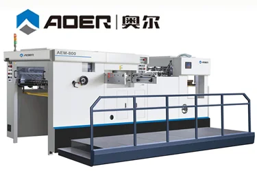
For shops that need to verify available pressure capacity against their specific material mix, understanding how different machine series are rated helps narrow down options. See how the automatic and manual die cutting machine in their pressure specifications, and review pressure capacity ranges across finishing equipment categories.
Flatbed or Rotary Die Cutting for Your Shop?
Understanding Die Make-Ready: From Test Sheets to Production Run
Five Hidden Costs of Cheap Die Cutting Machines


GET A QUOTE